الكود البرمجي (Processing)
انقر على الرابط التالي Processing وحمّل برنامج Processing حسب نوع نظام التشغيل المتوفر لديك.
بعد تحميله فك الضغط عنه وافتح البرنامج استعدادًا للبدء بالعمل عليه.
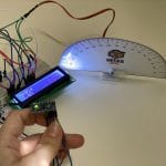
يساعدك الكود البرمجي بمحاكاة ورسم خط الأفق والتحكم به بواسطة حساس الحركة والتسارع.
في البداية عليك تنصيب مكتبة Arduino (firmata).
من قائمة sketch انقر على import library ثم Add library.
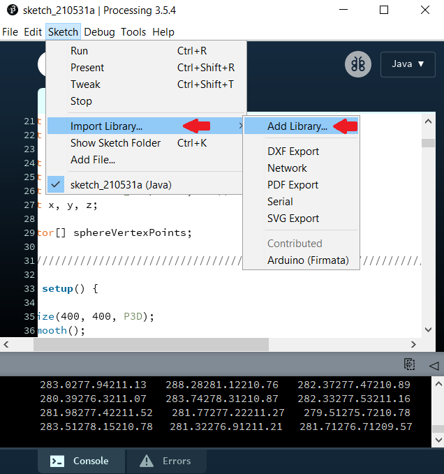
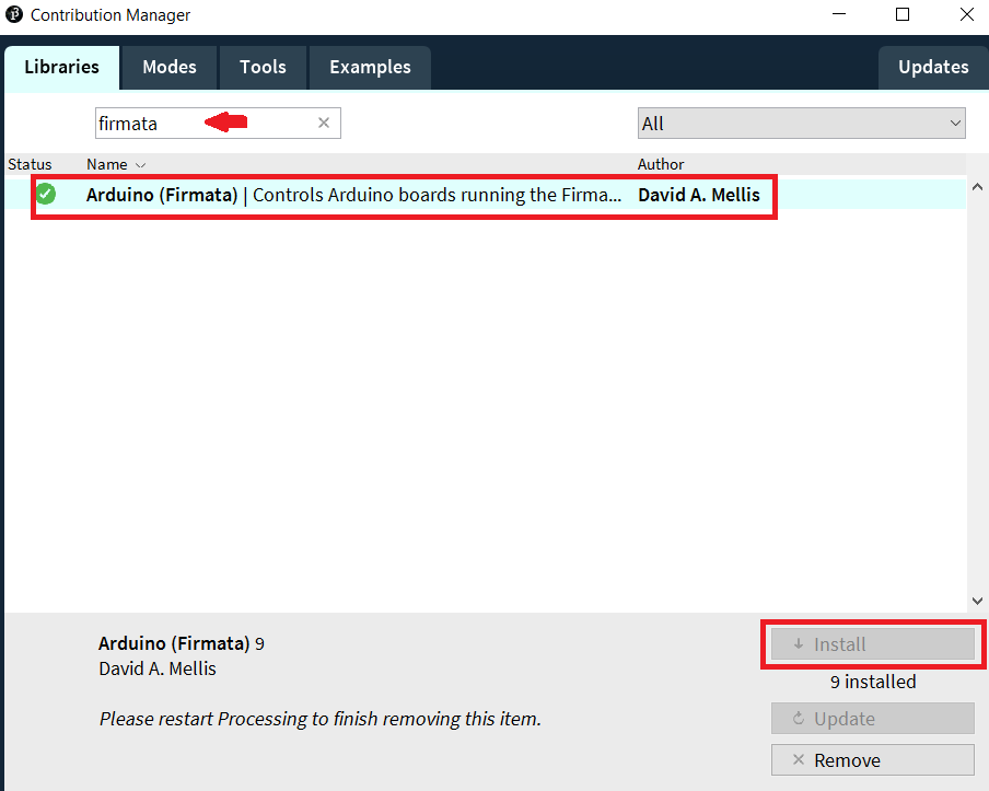
اكتب في خانة البحث firmata وانقر عليها وابدأ بتنزيلها كما هو موضح بالصورة.
قبل رفع الكود البرمجي الخاص بتمثيل خط الأفق إلى لوحة الاردوينو هناك أمور مهمة عليك تحريرها اقرأ شرح الكود البرمجي.
import org.firmata.*;
import cc.arduino.*;
import processing.serial.*;
import java.awt.event.KeyEvent;
import java.io.IOException;
import processing.opengl.*;

Serial myPort;
String data="";

float Pitch; // replaces roll and pitch
float Bank;
float Azimuth;

float Phi; //Dimensional axis
float Theta;
float Psi;

float radius = 250.0;
float rho = radius;
float factor = TWO_PI / 40.0; // detail is 40
float x, y, z;

PVector[] sphereVertexPoints;

void setup() {

size(400, 400, P3D);
smooth();

myPort = new Serial(this, "COM3", 9600); // starts the serial communication myPort.bufferUntil('\n');
}

void draw() {
background(0);
stroke(100);
strokeWeight(4);
fill(200);
rect(130, 10, 150, 50, 7); // (x,y,w,h, round corner dia)
fill(CLOSE);
fill(0);
rect(150, 30, 70, 25, 7);
fill(CLOSE);

strokeWeight(CLOSE); // very useful
fill(CLOSE);
stroke(CLOSE);

fill(0);
textSize(14);
text("Altitude: ", 150, 50, 50);
fill(CLOSE);
float y1 = y++;

float Alt = abs(Pitch/25+y1*10);

fill(0,255,255);
text(Alt, 160,70,50); // alt, x,y,z
fill(CLOSE);


fill(0, 0, 255);
textSize(12);
text(" m/s", 220, 70, 50 );
fill(CLOSE);

translate(width/2, height/2, -250); // camera placement
lights();


textLayer();
MakeAnglesDependentOnMPU6050();

fill(100);
circle(0,0,700); // dark gray circle
fill(CLOSE);

fill(150);
circle(0,0,670); // light grey circle
fill(CLOSE);

beginShape();

fill(255,255,0);
vertex(-14, -10, 300);
vertex(14, -10, 300); // yellow triangle, each vertex is x and y coords
vertex(0, -20, 300);
vertex(0, -20, 300);
stroke(0);
strokeWeight(2);
stroke(CLOSE);

endShape(CLOSE);


beginShape();
fill(255,255,0);
stroke(0);
strokeWeight(2);
stroke(CLOSE);
vertex(-50, -5, 300);
vertex( 50, -5, 300); // yellow line
vertex( 50, -10, 300);
vertex(-50, -10, 300);
fill(CLOSE);
endShape(CLOSE);


fill(210);
arc(-120, 0, 380, 525, PI/2, 3*PI/2); // left gauge fill
arc(120, 0, -380, -525, PI/2, 3*PI/2); // right gauge fill
fill(CLOSE);

pushMatrix();


rotateX(radians(Bank));
rotateZ(radians(Pitch)); // comment out to change to mouse
rotateY(radians(Azimuth));


// rotateX(radians(mouseY)); // comment in, to change to mouse.
// rotateY(radians(mouseX));
for(float PHI = 0.0; PHI < HALF_PI; PHI += factor) {

beginShape(QUAD_STRIP);
stroke(240);
strokeWeight(1);

for(float THETA = 0.0; THETA < TWO_PI + factor; THETA += factor) {

x = rho * sin(PHI) * cos(THETA);
z = rho * sin(PHI) * sin(THETA);
y = -rho * cos(PHI);

vertex(x, y, z);

x = rho * sin(PHI + factor) * cos(THETA);
z = rho * sin(PHI + factor) * sin(THETA);
y = -rho * cos(PHI + factor);

vertex(x, y, z);
fill(100, 100,255);
}
endShape(CLOSE);
}

for(float phi = 0.0; phi < HALF_PI; phi += factor) {
beginShape(QUAD_STRIP);
for(float theta = 0.0; theta < TWO_PI + factor; theta += factor) {
x = rho * sin(phi) * cos(theta);
z = rho * sin(phi) * sin(theta);
y = -rho * cos(phi);

vertex(-x, -y, -z);

x = rho * sin(phi + factor) * cos(theta);
z = rho * sin(phi + factor) * sin(theta);
y = -rho * cos(phi + factor);

vertex(-x, -y, -z);
fill(255,128,0);

}

endShape(CLOSE);

}
popMatrix();
/////////////////////////////////////////////////////////////////////
} // void draw
//////////////////////////////////////////////////////////////////////////
void textLayer() {


MakeAnglesDependentOnMPU6050();

/*pushMatrix();

rotateX(Bank/10);
rotateY(-Pitch/10);
rotateZ(Azimuth/10);

fill(255);

textSize(15);
text( "50", 0, 110, 230);
text( "90", 0, 180, 200);

popMatrix(); */

/////////////////////////////////////////////////////////

pushMatrix();

float y1 = y++;
float alt = abs(Pitch/25+y1*10+90);


beginShape();
rotateZ(alt);
stroke(255,255,0); // throttle measurement yellow
strokeWeight(8);
line(0,0,-310, 0);
stroke(CLOSE);
endShape();
strokeWeight(CLOSE);

popMatrix();

/////////////////////////////////////////////////////////////////////////////
int radius = 300;
int lines = 5*17;

for (int a=120; a<240; a=a+360/lines) {

float x = radius * cos(radians(a)); // gauge lines
float y = radius * sin(radians(a));


stroke(50);
line(0,0,x,y);
line(0,0,-x,-y);
strokeWeight(3);
stroke(CLOSE);

}

///////////////////////////////////////////////////////////

for (int a=120; a<160; a=a+360/lines) {

float x = radius * cos(radians(a)); // red gauge lines
float y = radius * sin(radians(a));

stroke(255,0,0);
line(0,0,-x,-y);
strokeWeight(3);
stroke(CLOSE);
}

for (int a=160; a<190; a=a+360/lines) {

float x = radius * cos(radians(a)); // orange gauge lines
float y = radius * sin(radians(a));

stroke(255,128,0);
line(0,0,-x,-y);
strokeWeight(3);
stroke(CLOSE);

}


for (int a=220; a<240; a=a+360/lines) {

float x = radius * cos(radians(a)); // red gauge max throttle
float y = radius * sin(radians(a));

stroke(255,0,0);
strokeWeight(3);
line(0,0,x,y);
stroke(CLOSE);

}

////////////////////////////////////////////////////////////////

}
///////////////////////////////////////////////////////////////////////
void serialEvent(Serial myport) { //Reading the datas by Processing.

String input = myport.readStringUntil('\n');

if (input != null) {

input = trim(input);
String[] values = split(input, " ");

if (values.length == 3) {

float phi = float(values[0]);
float theta = float(values[1]);
float psi = float(values[2]);

print(phi);
print(theta);
println(psi);

Phi = phi;
Theta = theta;
Psi = psi;
}
}
}

///////////////////////////////////////////////////////////////////////
void MakeAnglesDependentOnMPU6050() {

Bank = round(-Theta);
Pitch =round(-Phi-3);
Azimuth = round(Psi/700);


// Bank = -Phi/10;
// Pitch = Theta/10; // use these values for the ADXL345
// Azimuth = Psi/10;

}

/////////////////////////////////////////////////////////////////////////
شرح الكود البرمجي
هنا يتم استدعاء المكتبات الضرورية مثل org.firmata.* و cc.arduino.* و processing.serial.* و processing.serial.* و java.awt.event.KeyEvent و java.io.IOException و processing.opengl.*.
import org.firmata.*;
import cc.arduino.*;
import processing.serial.*;
import java.awt.event.KeyEvent;
import java.io.IOException;
import processing.opengl.*;
المتغير myPort من النوع Serial يحمل قيمة المدخل التسلسلي.
Serial myPort;
هناك مصطلحات يجب معرفتها:
float Pitch; // replaces roll and pitch
float Bank;
float Azimuth;
هنا يتم تعريف زوايا أويلر (Phi, Theta, Psi): هي ثلاث زوايا لوصف وجهة جسم صلب (الجسم الذي لا تتغير الأبعاد لنسبية بين نقاطه بتقدم الزمن) في الفضاء الإقليدي ثلاثي الأبعاد.
float Phi; //Dimensional axis
float Theta;
float Psi;
هنا يتم تعريف المتغير radios نصف القطر ويحمل القيمة 250.0.
والمتغير rho يأخذ نفس قيمة المتغير radios.
المتغير factor يأخذ القيمة TWO_PI هو ثابت رياضي بقيمة 6.28318530717958647693 ضعف نسبة محيط الدائرة إلى قطرها مقسوم على 40,0.
المتغيرات x,y و z يتم قراءة قيمها من حساس الحركة والتسارع في ثلاث اتجاهات.
float radius = 250.0;
float rho = radius;
float factor = TWO_PI / 40.0; // detail is 40
float x, y, z;
[]PVector هو عبارة عن class يتم فيه وصف الأبعاد الثنائية والثلاثية الأبعاد.
هنا سيتم استخدام مجسم ثلاثي الأبعاد كروي.
PVector[] sphereVertexPoints;
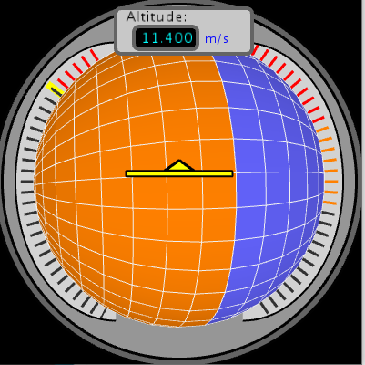
شكل المجسم المستخدم في الدرس:
في الدالة ()setup:
يتم توضيح حجم المجسم الكروي ثلاثي الأبعاد size(400, 400, P3D).
وهنا myPort = new Serial(this, “COM3”, 9600) يتم تحديد قيمة مدخل الاتصال التسلسلي. (هذا السطر قابل للتحرير بناء على القيمة الموجودة لديك).
void setup()
{
size(400, 400, P3D);
smooth();
myPort = new Serial(this, "COM3", 9600); // starts the serial communication myPort.bufferUntil('\n');
}
في الدالة ()draw سيتم تعيين لون الخلفية باللون الأسود ويساوي القيمة 0.
void draw()
{
background(0);
سيتم رسم مستطيلان لتوضيح الارتفاع Altitude.
المستطيل الأول مغلق بلون رمادي قيمته 200 وحدود قيمتها 100.
مكانها على محور x= 130 وعلى محور y=10 عرضها=150 طولها= 50.
stroke(100);
strokeWeight(4);
fill(200);
rect(130, 10, 150, 50, 7); // (x,y,w,h, round corner dia)
fill(CLOSE);
المستطيل الثاني مغلق بلون أسود قيمته 0.
مكانها على محور x= 150 وعلى محور y=30 عرضها=70 طولها= 25.
fill(0);
rect(150, 30, 70, 25, 7);
fill(CLOSE);

strokeWeight(CLOSE); // very useful
fill(CLOSE);
stroke(CLOSE);
fill(0);
textSize(14);
text("Altitude: ", 150, 50, 50);
fill(CLOSE);
المستطيل الأول سيكتب داخله الارتفاع Altitude وحجم الخط 14.
textSize(14);
text("Altitude: ", 150, 50, 50);
fill(CLOSE);
المستطيل الثاني سيكتب داخله قيمة الارتفاع Altitude.
float Alt = abs(Pitch/25+y1*10);

fill(0,255,255);
text(Alt, 160,70,50); // alt, x,y,z
fill(CLOSE);
وفي نهاية يمين المستطيل سيتم كتابة الوحدة المستخدمة باللون الأزرق.
fill(0, 0, 255);
textSize(12);
text(" m/s", 220, 70, 50 );
fill(CLOSE);
سيتم رسم دائرة لونها رمادي غامق.
fill(100);
circle(0,0,700); // dark gray circle
fill(CLOSE);
ودائرة باللون المادي الفاتح.
fill(150);
circle(0,0,670); // light grey circle
fill(CLOSE);
هنا سيتم رسم المثلث الصغير الذي سيظهر بالمنتصف.
fill(255,255,0);
vertex(-14, -10, 300);
vertex(14, -10, 300); // yellow triangle, each vertex is x and y coords
vertex(0, -20, 300);
vertex(0, -20, 300);
stroke(0);
strokeWeight(2);
stroke(CLOSE);

endShape(CLOSE);
هنا سيتم رسم الخط الأصفر.
beginShape();
fill(255,255,0);
stroke(0);
strokeWeight(2);
stroke(CLOSE);
vertex(-50, -5, 300);
vertex( 50, -5, 300); // yellow line
vertex( 50, -10, 300);
vertex(-50, -10, 300);
fill(CLOSE);
endShape(CLOSE);
هنا سيتم رسم الخطوط الصغيرة المتقطعة على حدود المجسم الكروي.
fill(210);
arc(-120, 0, 380, 525, PI/2, 3*PI/2); // left gauge fill
arc(120, 0, -380, -525, PI/2, 3*PI/2); // right gauge fill
fill(CLOSE);

pushMatrix();
سيكون التحكم بخط الأفق من قبل المستخدم بواسطة حساس الحركة والتسارع.
rotateX(radians(Bank));
rotateZ(radians(Pitch)); // comment out to change to mouse
rotateY(radians(Azimuth));


// rotateX(radians(mouseY)); // comment in, to change to mouse.
// rotateY(radians(mouseX));
سيتم رسم شريط رباعي الشكل على المجسم الكروي.
ودوران x,y و z بناء على القيم المقروءة من الحساس.
وسيتم استبدال Alt بالقيمة التي تم احتسابها.
for(float PHI = 0.0; PHI < HALF_PI; PHI += factor) {
beginShape(QUAD_STRIP);
stroke(240);
strokeWeight(1);

for(float THETA = 0.0; THETA < TWO_PI + factor; THETA += factor) {
x = rho * sin(PHI) * cos(THETA);
z = rho * sin(PHI) * sin(THETA);
y = -rho * cos(PHI);

vertex(x, y, z);
x = rho * sin(PHI + factor) * cos(THETA);
z = rho * sin(PHI + factor) * sin(THETA);
y = -rho * cos(PHI + factor);

vertex(x, y, z);
x = rho * sin(phi + factor) * cos(theta);
z = rho * sin(phi + factor) * sin(theta);
y = -rho * cos(phi + factor);
vertex(-x, -y, -z);
fill(255,128,0);
}
endShape(CLOSE);
}
popMatrix();
/////////////////////////////////////////////////////////////////////
} // void draw
//////////////////////////////////////////////////////////////////////////
سيتم حساب قيمة الارتفاع بناء على القيم المقروءة من حساس الحركة والتسارع في ثلاث اتجاهات.
void textLayer() {
MakeAnglesDependentOnMPU6050();

/*pushMatrix();

rotateX(Bank/10);
rotateY(-Pitch/10);
rotateZ(Azimuth/10);

fill(255);

textSize(15);
text( "50", 0, 110, 230);
text( "90", 0, 180, 200);

popMatrix(); */

/////////////////////////////////////////////////////////

pushMatrix();

float y1 = y++;
float alt = abs(Pitch/25+y1*10+90);
هنا سيتم تدوير المثلث الأصفر بناء على قيمة Alt.
beginShape();
rotateZ(alt);
stroke(255,255,0); // throttle measurement yellow
strokeWeight(8);
line(0,0,-310, 0);
stroke(CLOSE);
endShape();
strokeWeight(CLOSE);
الخطوط المتقطعة على جوانب المجسم ستكون باللون الأسود والأحمر والبرتقالي.
int radius = 300;
int lines = 5*17;

for (int a=120; a<240; a=a+360/lines) {

float x = radius * cos(radians(a)); // gauge lines
float y = radius * sin(radians(a));


stroke(50);
line(0,0,x,y);
line(0,0,-x,-y);
strokeWeight(3);
stroke(CLOSE);

}

///////////////////////////////////////////////////////////

for (int a=120; a<160; a=a+360/lines) {

float x = radius * cos(radians(a)); // red gauge lines
float y = radius * sin(radians(a));

stroke(255,0,0);
line(0,0,-x,-y);
strokeWeight(3);
stroke(CLOSE);
}

for (int a=160; a<190; a=a+360/lines) {

float x = radius * cos(radians(a)); // orange gauge lines
float y = radius * sin(radians(a));

stroke(255,128,0);
line(0,0,-x,-y);
strokeWeight(3);
stroke(CLOSE);

}


for (int a=220; a<240; a=a+360/lines) {

float x = radius * cos(radians(a)); // red gauge max throttle
float y = radius * sin(radians(a));

stroke(255,0,0);
strokeWeight(3);
line(0,0,x,y);
stroke(CLOSE);

}
إمكانية الوصول للبيانات المقروءة من الحساس عن طريق المنفذ الناقل التسلسلي.
void serialEvent(Serial myport) { //Reading the datas by Processing.

String input = myport.readStringUntil('\n');

if (input != null) {

input = trim(input);
String[] values = split(input, " ");

if (values.length == 3) {

float phi = float(values[0]);
float theta = float(values[1]);
float psi = float(values[2]);

print(phi);
print(theta);
println(psi);

Phi = phi;
Theta = theta;
Psi = psi;
}
}
}
في الدالة ()MakeAnglesDependentOnMPU6050 يتم إسناد قيمة Bank و Pitch و Azimuth بناء على القراءات من حساس الحركة والتسارع في ثلاث اتجاهات.
void MakeAnglesDependentOnMPU6050() {

Bank = round(-Theta);
Pitch =round(-Phi-3);
Azimuth = round(Psi/700);


// Bank = -Phi/10;
// Pitch = Theta/10; // use these values for the ADXL345
// Azimuth = Psi/10;

}
يمكنك اختبار محاكي خط الأفق الخاص بك.
لا تنسَ فصل مصدر الطاقة بعد الانتهاء من استخدام النظام.